
We recently decided to go down the road of upgrading our old camp trailer to a new Air Opus. The rationale was to make setup and tear down significantly easier.
So we visited the Caravan and Camping Show and before I knew it we had bought one! We have had it out three times this year so far, and typically get out about 4 times a year. So now I’m keen to see if I can get the family out for a winter camp at some stage.
What’s keeping us? Parts of the family are thermally challenged. So, continuing with the theme of “If they’re compfortable enough, they will come”, I decided to go buy a diesel heater for Opie (my wife’s name for the new trailer).
But what to buy?
So the first thing was to figure out whether to go buy an expensive Eberspaecher unit (at around $1800), or a cheaper chinese model (around $200).
After doing some research on the net (there is plenty of information out there on these units) I made the call to buy a Chinese model off Ebay. The heaters are actually very simple units. There is a sealed chamber in which fuel is injected and ignited initially by a glow plug. Once the unit is hot enough, the fuel self ignites in the combustion chamber. That heats the chamber, which has a set of fins formed around it. Air from the room gets blown over the fins which are now a big heat exchanger and wonderfully hot air flows out of the outlet.
So, they’re very simple devices, with only one moving part (the fan, which is driven by a small motor… in fact it’s two fans on a single spindel, one to move the room air over the heat exchanger, and another to blow air into the combustion chamber…). On that basis I decided to jump onto the chinese heater bandwagon and give it a shot.
After that you need to decide whether to go 2kW or 5kW. I opted for 5kW with the theory that I could run the unit slower than the 2kW unit for a given temperature. Running a unit hard usually decreases it’s usable lifespan considerably. It turns out I made the right choice, but more on that later.
3 days later a large box arrived…
Hurdle 1: Will it work?
Confident that I had all the information I needed, I decided to first set it up in the garage to make sure it was all working as expected.
So I mounted the heater into some plywood and hooked it all up. I used my old trailer battery to power the unit (it will draw up to 12A, so you’ll need something much bigger than your average 12VDC power supply 🙂
The first burn up was straight forward… everything went according to plan. A couple more longer runs and I was confident the unit was in good working order. So, onto the next hurdle…
Hurdle 2: Where to put it?
Ive seen a few people mount these units into the long storage bays in the trailer, but they appear to take up a significant amount of space. Looking at the dimensions, it looked like it would fit in a much smaller space (the little compartment in which the battery charger is mounted), but why had others not done the same?
For a start there is only direction to mount it in that would work. Then, the smaller space was going to make the installation more difficult. I didn’t want to loose the storage space though, so, nervously, I proceeded thinking I’d mount it in there.
So I added the domensions of the charger box to my plywood mount and found there was going to be no physical problem getting it in there. And in fact putting it in the right place gave it a perfect channel to push warm air out! Happy days!
Hurdle 3: Hurting my new Opus trailer!
D-Day came and biting the bullet to cut into the trailer floor was, as expected, a little daunting. I didn’t want to wind up cutting into the floor only to find it was in the wrong position.
So I took my plywood template under the trailer and tried to locate it (from a cable gland that’s already there).
Bugger!
I found a structural member that ran right through the place I had intended to mount the unit. So cutting where I had hoped to wasn’t going to work.
At this stage I was stuck, thinking I had found why people were not using the smaller space. And then…
I read the specs…
Its impossible to tell from the chinese documentation (and hard from the Eberspraecher docs too!) but in the illustration showing the dimensions of the unit, it specifies the minimum clearance from the back of the unit for the air intake. That’s 30mm. Not a lot of space, but I fear more than I had to play with.

At this stage I couldn’t get away with any further non-destructive investigation. So I took a 2mm drill bit under the trailer and popped a pilot hole through the floor right next to the structural member, approximately where I thought the middle of the unit would be. That determined where I would be able to place the outlets.
Going back up top and putting the unit in place I found that there was almost exactly 30mm clearance at the rear of the unit if I used that mounting placement. Looks like it was almost made for purpose!

Aim for perfection, or get on with doing a good enough job?
I had the dimensions of the port layout for the unit, and had used these to cut out the holes in the template, although this was a bit of a tight fit and left no room for error.
The unit comes with a reinforcement place, which allows you to cut a rectangle out and place screw the unit in place without worrying about missing a bolt or port hole by a few millimetres.
So I ended up deciding to go down that road.
Getting on with the job
I always find that after I’ve drilled one hole, further damage doesn’t cause as much pain… so I set about preparing the area for mounting.
First I placed the reinforcing plate down and cut the lino around it.


The flooring composition 
Rough dimensions to position the cut 
Pilot holes for the jigsaw 
Get rid of the old adhesive to create the best possible surface for the new silicon 
Checking from underneath to know how close to the structural beam I am… phew!!! 
No turning back now… 
And done… 
Perfect!
The floor is a 1.5mm linoleum layer, over a 5mm sponge underlay, over a 6.3mm plywood substrate and finally 1.3mm of steel plate.
I wanted to get rid of the lino and underlay to give the unit a more firm seal to the floor (and to make sure the cloor covering wasn’t exposed from under the trailer). So I cut out the lino and underlay, and scraped away all the remaining contact adhesive. I then marked out the rectangle I wanted to remove, and drilled out each of the four corners.
Then with a metal jigsaw blade I cut through the floor, finishing the rough cut off with a file.
Sealing it up again
Having cut open my precious Opus, and knowing full well I intended to get it wet through rivers, I got hold of some Selleys 401 Engineering Silicon and spread that out over the exposed plywood, smearing it over the edges (to protect them from moisture also), and put the reinforcing plate down.

Put down a decent layer of 401 Silicon, which will act both as an adhesive and a sealant from outside 
Smear it out with a paint scraper or a scrap of wood 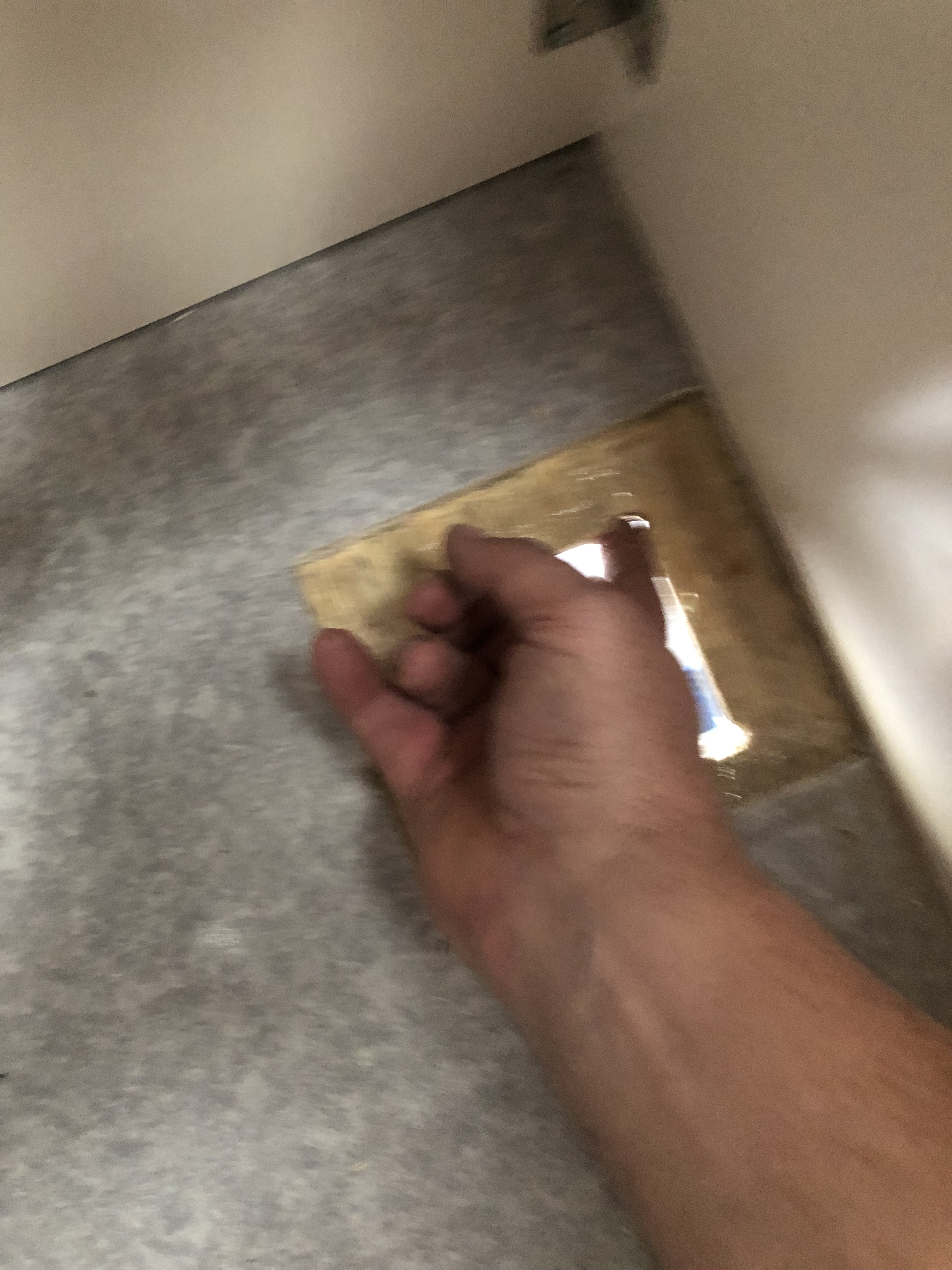
Run some of the excess silison around the timber and metal edges to seal those from the elements 
Once you screw down the plate, lay down some silicon sealant around the lino/underlay just for good measure…
Make sure you check that the fit is right and you can get the exhaust hose on with a hose clamp before you get to this stage – you won’t be removing this plate without damage if you use the 401 silicon – amazing stuff!
And with the reinforcing place in position, time for the last step of screwing it to the floor with the tec screws provided (this is really only to stop it moving while the silicon goes off – I’m pretty confident it’s going nowhere once it’s set!)
Let the silicon cure for an hour or two before proceeding – You don’t want to end up with the unit’s gasket stuck to the plate because you didn’t clean the surface of any stray silicon!
Fuel System
Some indecision and finally settling on the most sensible option for fuel storage – put the fuel out on one of the two jerry can holders. I toyed with having it inside but at the end of the day I didn’t want to risk the smell of kerosene (more on that later) permeating through the cabin. Since the combusion chamber is sealed, and the fuel live is ported out of the vehicle, it made little sense to bring it back inside.
I took a heavy duty black fuel container (just a 10 litre one for now), and adapted it by putting the fuel pickup from the fuel tank that comes with the unit into the bottom. This is straight forward, but tricky if you haven’t done it before.
Start by locating a flat surface in the tank – you need this to get a good seal. And place it roughly an inch off the bottom – yes there will be unused fuel in the can, but that’s also where all the rubbish will settle (and you don’t want that in your burner!)
Now drill a 2mm pilot hole, being careful to do it slowly so that all the drill cuttings fall out of the can rather than being pushed into the can.

Then grab a drill bit that is only just the width of the thread and again, slowly, drill out the hole as cleanly as you can.
Then find an old coat hanger and straighten it. Now put a small 90 degree bend in the end and insert that into the fuel pickup. Place one of the orings into the seat at the bottom of the thread.

The coat hanger should be snug, but not require force to insert!
And then the tricky bit. You need to “fish” the pickup in through the jerry openning and thread the nut onto the pickup. You can grip the tube down close to the thread to help tighten the nut, but do NOT crush it!
Test the seal by putting a finger over the fuel barb and blow into the can openning – there should be no air escaping the seal.

Not easy to see here, but I have the coathanger inserted to try to find the hole I drilled. 
If you are going to grip the barb, do so near the nut thread – don’t damage the barb head!
For the last test, you can use the black plastic cover that was on the heater fuel inlet over the fuel barb and put a bit of fuel into the tank.
The clock (or rather the pump) is ticking
The next problem you will encounter is the noisy little dosage fuel pump. I’ve had a crack at isolating that by housing the pump in an enclosure instead of mounting it directly.
I drilled holes for the fuel line (through cable glands to keep the weather out) so that the pump is aligned straight through the box – meaning that the box will need to be mounted at a 45 degree angle. I felt it was more important to avoid any bends in the juntion between the nylon fuel line and the black fuel line.

Always start with a pilot hole… 
Then use a 14mm bit for the larger cable gland 
And clean up the hole with a file… 
This ridge needs to be removed so the gland will screw on… 
… to look like this – I used a sharp chisel for this job 
Here’s the fitten gland 
This is the pump with fuel line connected 
Then I’ve filled the enclosure with acoustic wool here, but it’s not enough for the job… 
And the final box needs to be mounted at 45 degrees as per the installation directions
Unfortunately although the ticking is less pronounced to the outside world, it still transmits through the Opus frame, so I will have to try a few other things to get this part of it right…
Closing up the patient
Next job is to screw down the unit, fit the air outlet and hook up the electricals. The unit fits like a glove and leaves just 30 mm behint the inlet as prescribed.

The desk gland that allows access to the 240V point (which the charger is connected to pretty much permanently for me) is replaced with the second vent as an air intake, and appears to provide sufficient airflow to run the unit (I had it running for three hours today).
The outlet goes through both the box sidewall and the 16MM board that supports my bed extension, so I cut a 74mm hole in the box wall, and 103mm in the 16mm board (I ran black silicon around the inside of the hole I cut to make it look better).

The fuel pump cable needs to have the plug cut off to get through the blands under the charger. Then I ran the cable alongside the existing wiring loom and up to the fuel pump. Just leave about 100mm of cable near the end of the connector so you can reconnect it. I’ve put the original connector inside the pump box, and have reconnected the cable using a weatherproof 2 pin connector from Autobahn).
The battery line needs extending too, because they don’t provide enough lead for the negative terminal. My solution was to cut both at about 100mm, and add a metre of 16AWG copper cable (as a sheathed pair from Jaycar https://www.jaycar.com.au/15a-twin-core-power-cable-sold-per-metre/p/WH3079) using butt crimp connectors (https://www.jaycar.com.au/butt-connector-blue-pk-100/p/PT4628). Eventually I’m going to put an isolator switch in for this unit.
Exhausting!
Finally, hooking up the exhaust. I’ve chosen to not mount the exhaust and air intake permanently. Instead I will carry those in the storage bin. I’ve picked up a coupld of 25mm chair stoppers from Clark Rubber, with hose clamps, to go over the ports while we are driving.
Then the exhaust and intake hang freely, which has the added benefit of reduced noise through the chasis.
For the air intake I’ll be picking up a small motorbike air filter to use instead of the supplied hose and mesh filter.
Testing, 1, 2, Testing…
Once everything is hooked up and double checked you can go ahead and fire it up. Don’t forget to unscrew the fuel cap a little to allow the tank to breathe. I found that with an ambient temperature of 8 degrees, it took about 15 minutes to worm up to an internal temp of 21 degrees, which was pretty comfy. Under those conditions the pump continues to run at around 2.4 Hz, which is about half speed. So I’m pretty happy I didn’t go for the 2kW model.
Next steps
There are a couple of loose ends I hjave to get to tomorrow, including:
- sheathing the fuel line in coolant line to keep it protected from stones and dust
- Putting a fuel cut-off value inline to protect against any accidental activation of the heater while the camper is packed down
- creating a new panel mount for the controller that better hides the cable and has a flip door to blank off the light from the controller at night.
I’ll follow up with another post about these last bits shortly, and try to get around to posting some acurate comensions for the cutting…
